
By Keith Johnson

If you follow me on social media you know my wood species of choice has long been air-dried walnut. I love the variety of hues and depth of pattern that you don’t normally find in kiln-dried lumber. However, my tastes have recently shifted a little more towards mid-century modern furniture and the subtle beauty of straight-grained white oak. These end tables are the offspring of a console table I built earlier this year called the “Sophia.” That piece took inspiration from many other modern style pieces I found while scouring the internet. These end tables will now expand the “Sophia” collection, which will also include a buffet and a hall cabinet coming in 2020. Quarter-sawn white oak is most well-known in Craftsman-style furniture for its incredible contrasting grain pattern and ray flecks. My taste is a little different and I specifically look for straight-grained white oak…without the ray flecks. Both the original “Sophia” console table and these end tables use 3/4" white oak veneer plywood with solid white oak legs and case trim. If you want to build the tables completely from solid stock, there’s no reason not to…it would just mean a bit more milling and gluing up.
I built the “Sophia” console table with nothing more than a hand drawn sketch on a piece of scrap paper and a lot of “on-the-fly” adjustments. This time, I used SketchUp to do a complete 3-D drawing and material list. A half-sheet of plywood is sufficient for two end tables. Take your time with the shopping process for both sheet goods and solid stock. Make sure you’re going into the build with exactly the material you want…and a little bit to spare.
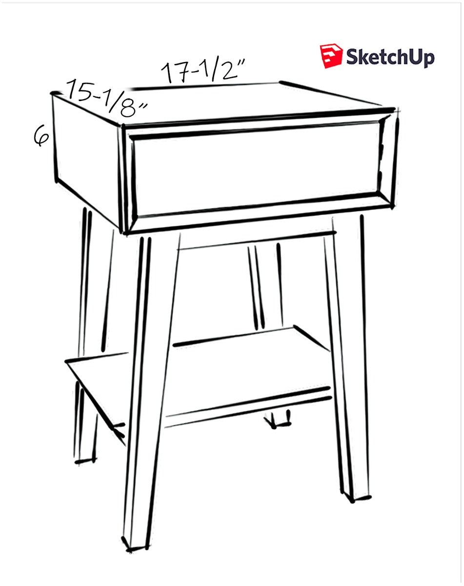
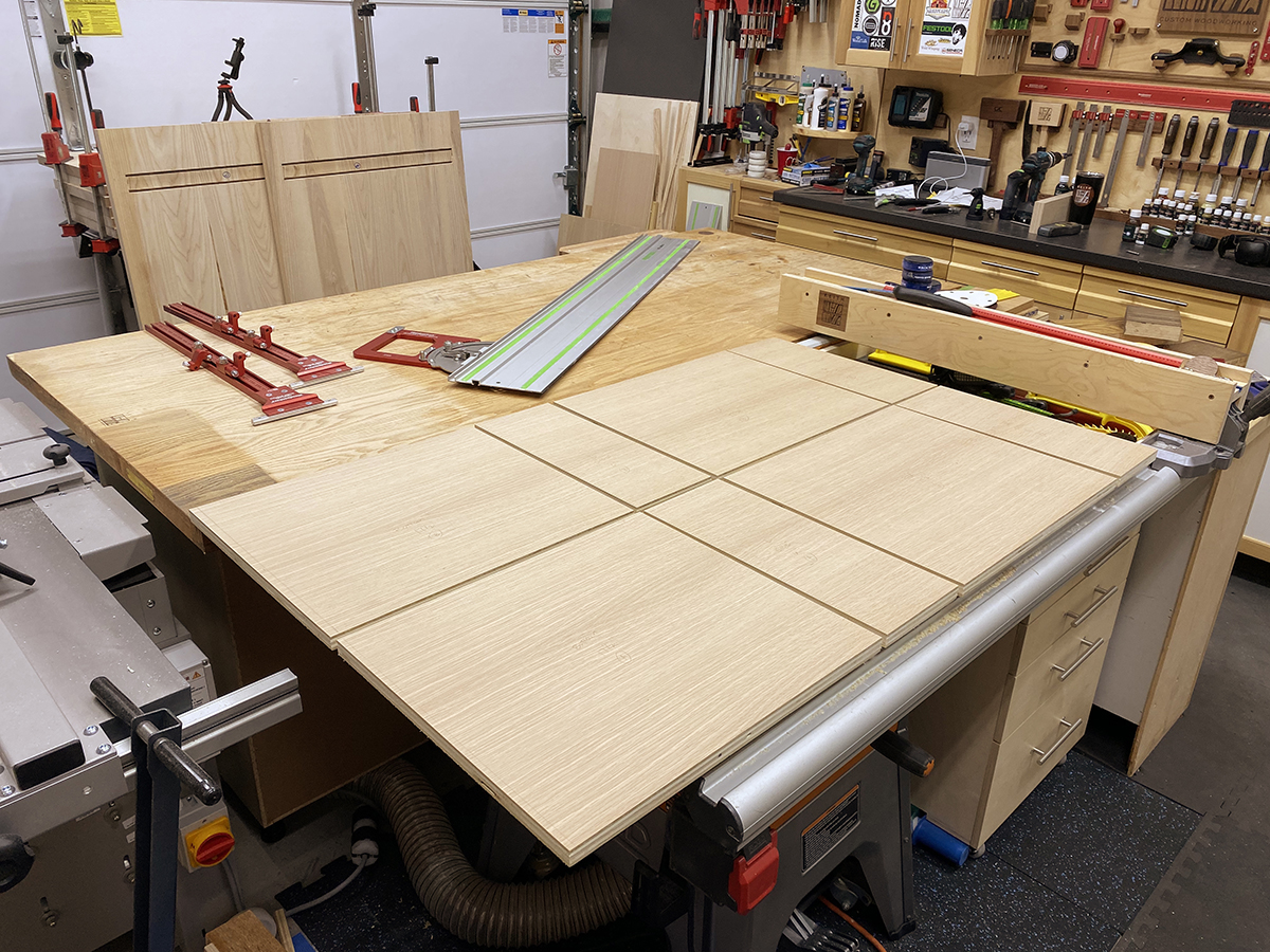
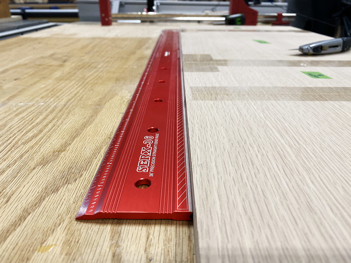
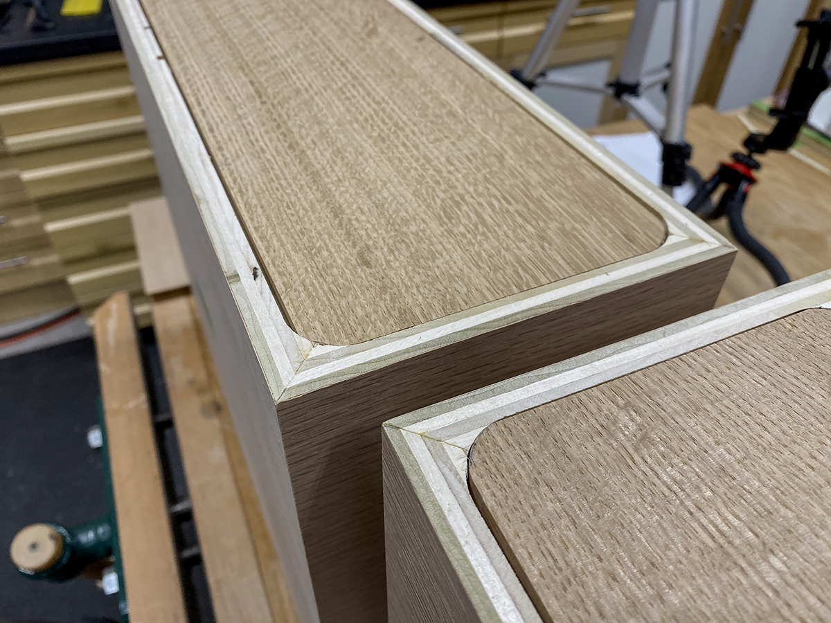
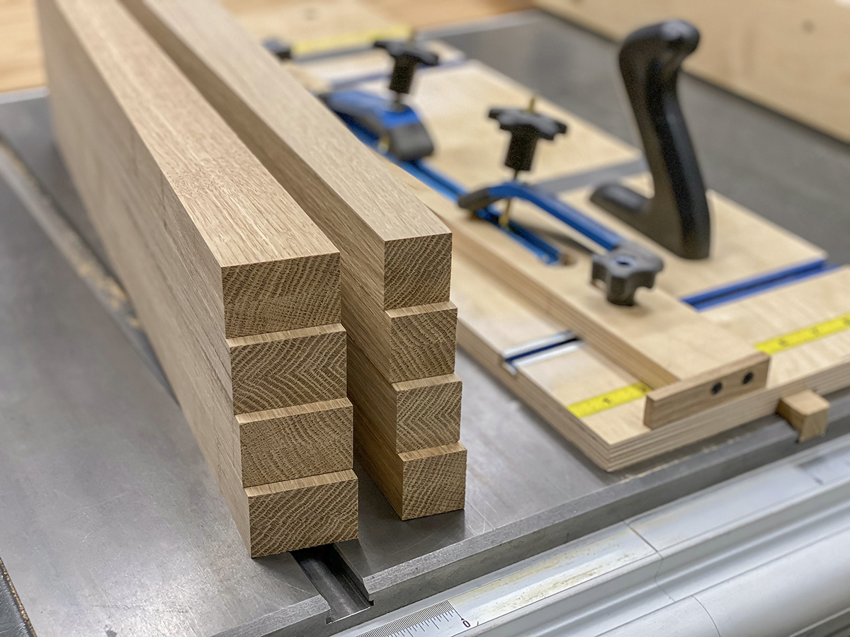
I used the Woodpeckers Parallel Guide System and Adjustable Track Square in conjunction with my Festool track saw to cut the plywood for the cabinets to size. I wanted a continuous grain pattern flowing around the mitered corners, so I began by ripping two sections 15-1/8" wide and 48" long. Next, I laid out my cross cuts, cutting a side, the top, the other side, and the bottom in order. This keeps the grain flowing around the corners perfectly, with one exception (but it will be on the bottom). The sides are 6” and tops and bottoms are 17-1/4”.
Bottom-end-top-end layout gives waterfall grain match around top corners.
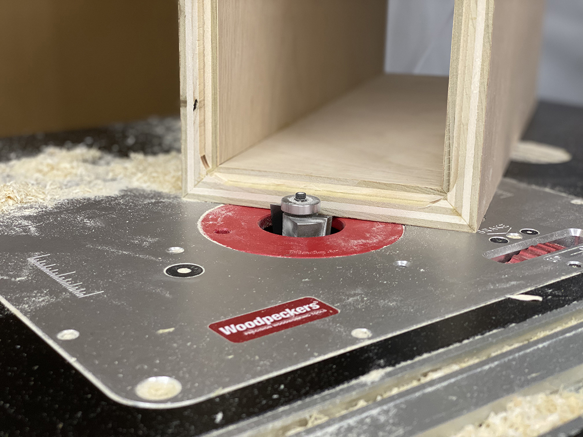
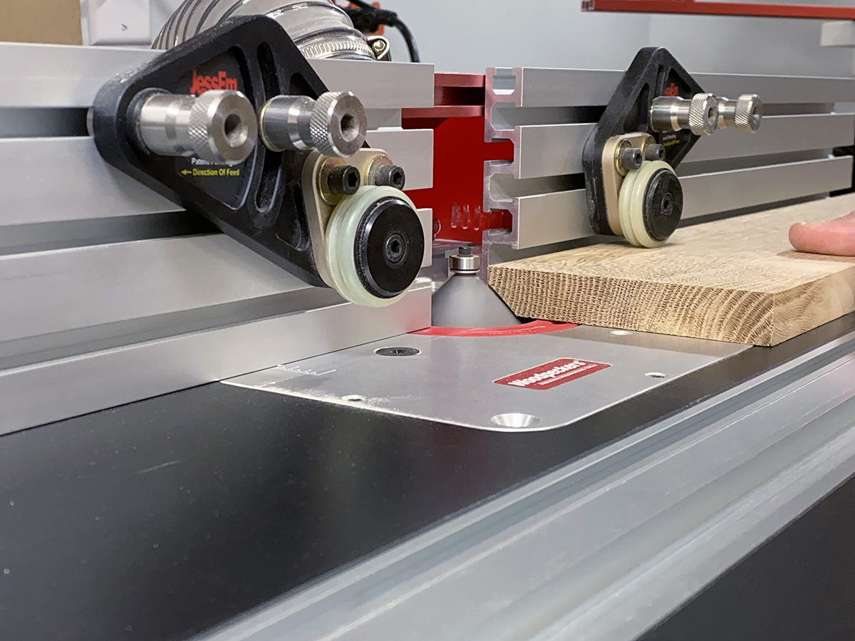
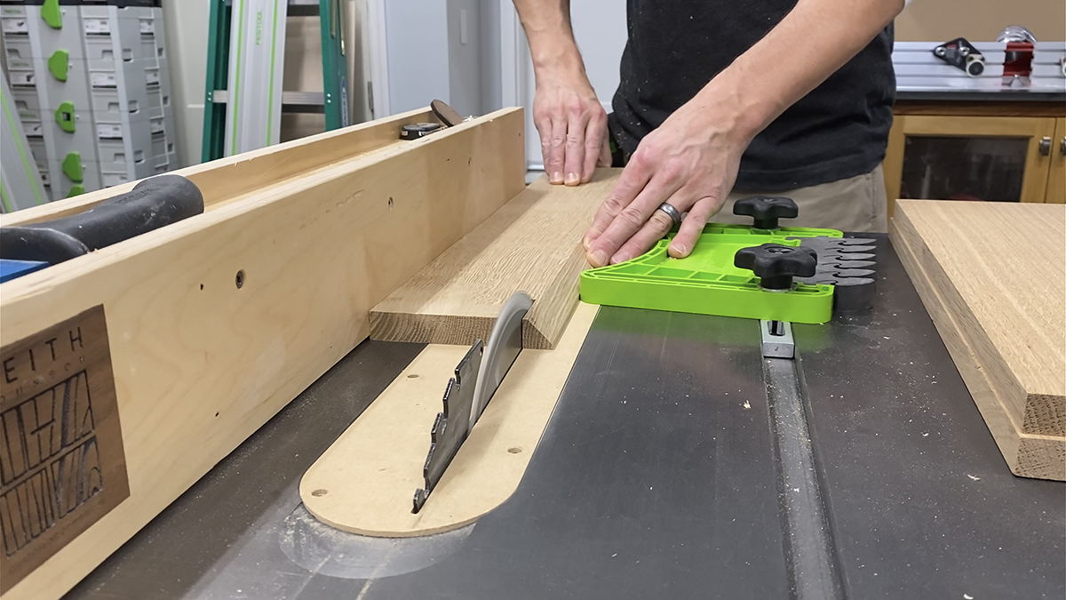
There are lots of options for cutting the 45° bevels on the plywood edges, and I’ve tried just about all of them. I have the most consistent results when I use a large chamfering bit in my Woodpeckers Router Table. Since the 45° angle is actually part of the cutter, rather than an equipment set-up, it takes less time and delivers very accurate results.
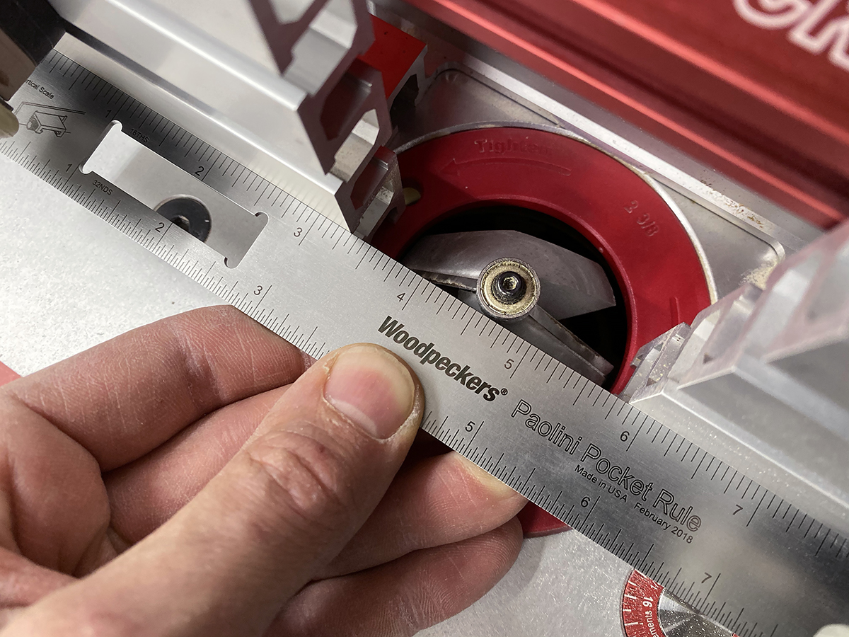
Align fence just forward of the guide bearing.
In setting the fence for this cut, I wanted to keep the material away from the bearing. I didn’t want the bearing to damage the crisp edge of the bevel. I used the Micro Adjust on the Woodpeckers Super Fence to dial the fence in just a bit forward of the bearing. Next, I brought the bit up to a height just a little lower than the thickness of my plywood. I made test cuts, raising the bit up with the thumbwheel a few thousandths at a time until the bevel was cutting perfectly flush with the surface. Once the height was dialed in, I locked it down to prevent any vertical movement in the router lift.
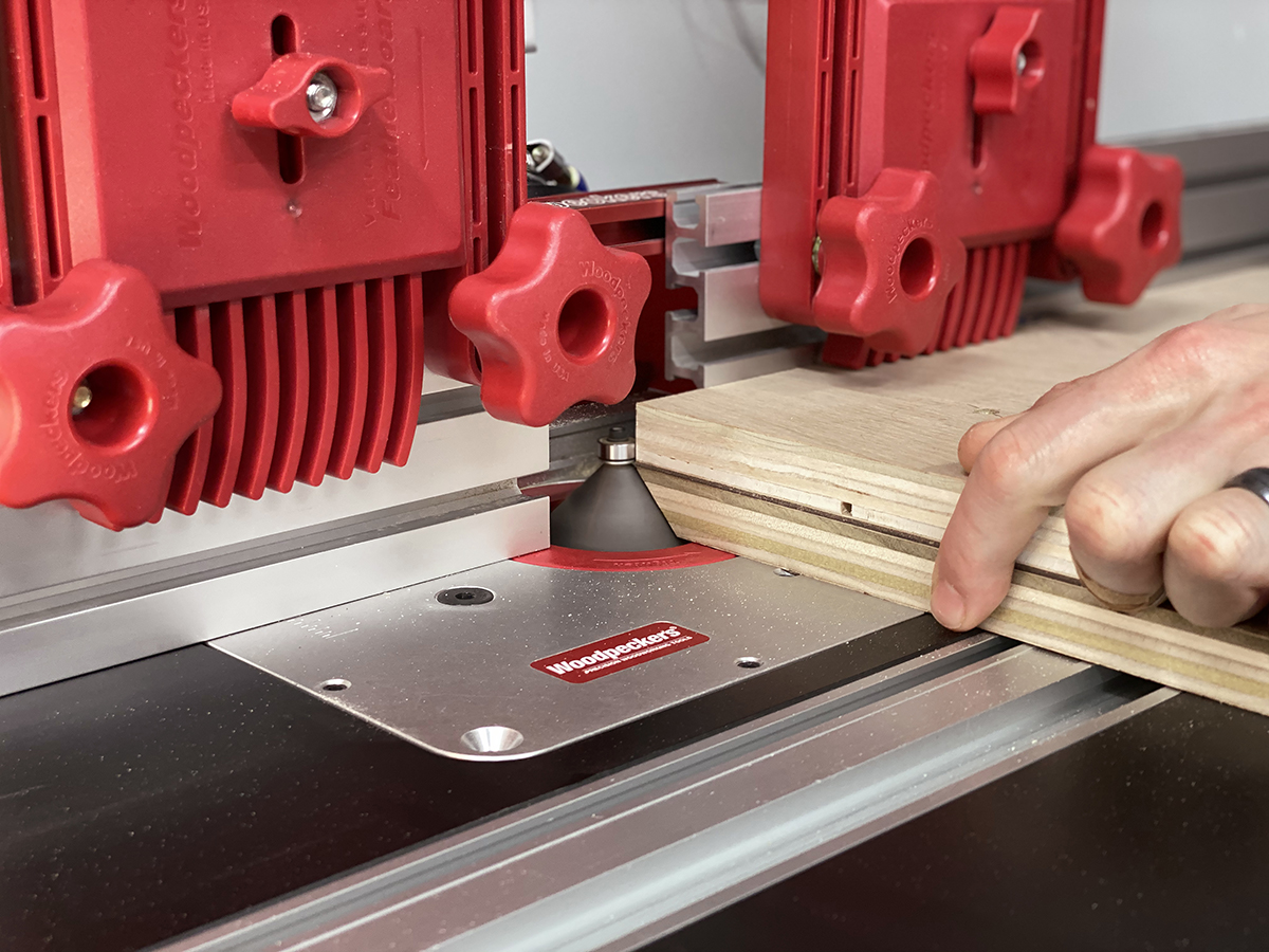
Scrap attached to top of work to protect edge.
After passing the cutter, the finished bevel is vulnerable to damage. I didn’t want to crush the edge pushing it into the outfeed fence, so I decided to support it with a sacrificial guide block (Jeff used a similar technique in his lock miter keepsake box on page 48). I attached the sacrificial board to the top of my workpiece with double-sided tape. This basically became the reference edge and provided a true surface to ride along the fence. I added a hardwood cleat to the back of my new push block to support the exit point and prevent any tear-out. This is critical since the pieces were already cut to final dimension. I attached a Featherboard to the Super Fence for downward pressure. After one more test cut, I machined the mating edges of the cabinets.
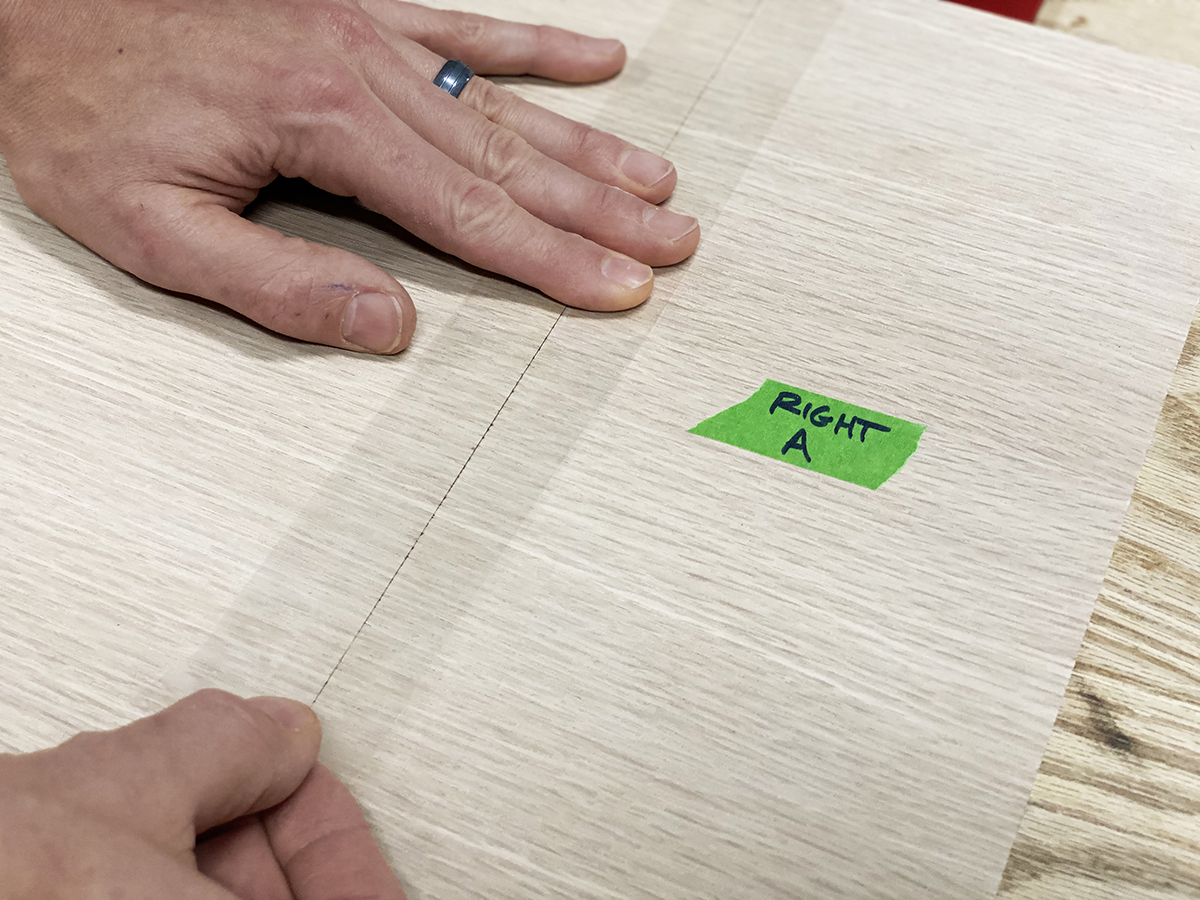
Edges aligned with straight-edge for taping.
Since the boxes are sort of short, I sanded the inside surfaces before I glued them together. Had I been smart, I would have applied the finish as well, but I chose to save that part until the end when it’s much more difficult. The assembly process reminds me of grade school art projects…it’s all about careful application of tape and glue. I laid all my pieces out in succession with the miter tips touching each other. I placed the flat edges against a straight edge to ensure they were all in line. I taped each joint with clear packing tape. When I first saw this technique, it was with masking tape, but packing tape has a little stretch to it and you can see through it to double check there are no gaps in your joinery.
Packing tape used to connect edges.
Packing tape used to connect edges.
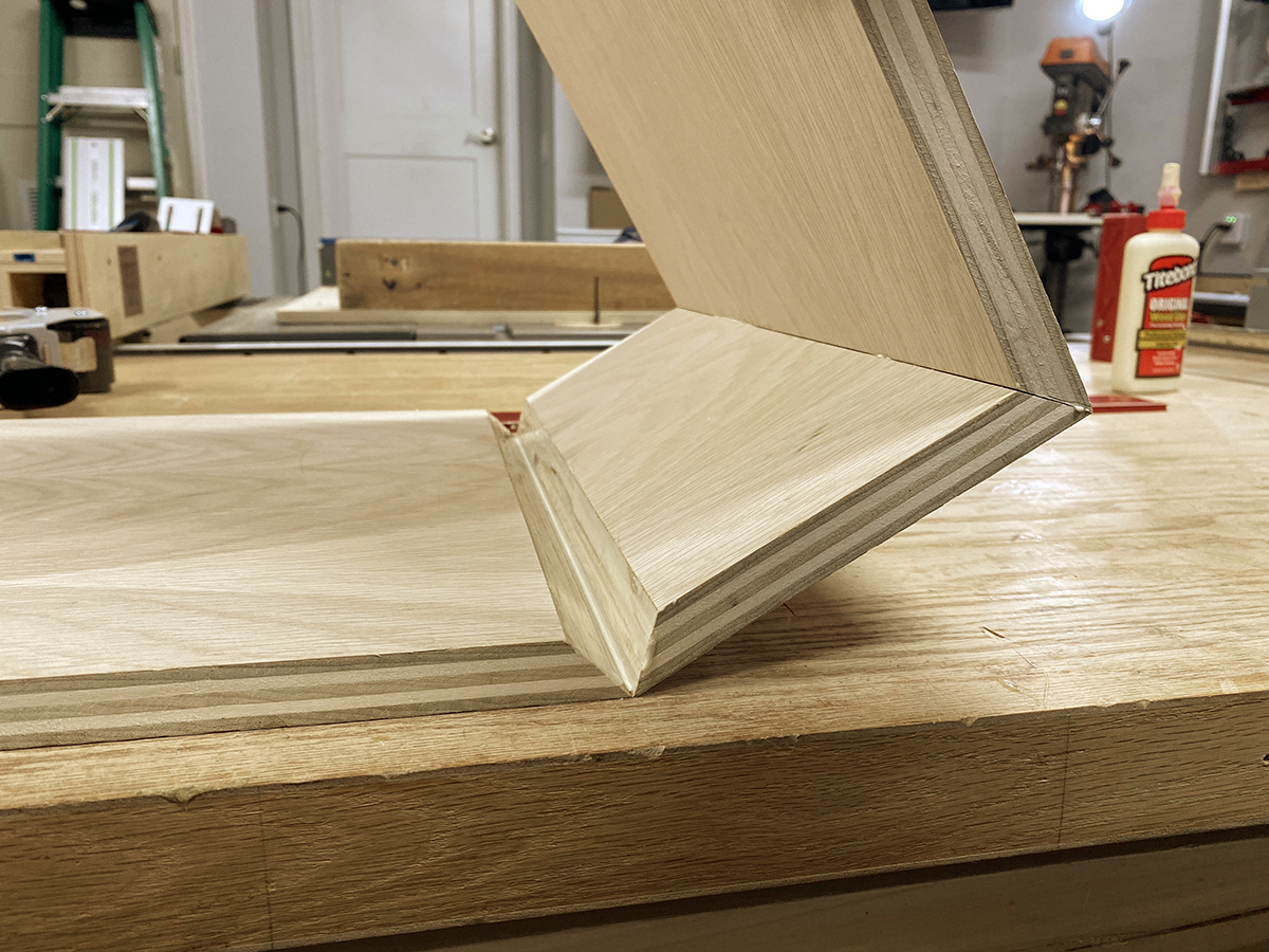
Once the tape was applied to all the joints, I flipped the whole assembly over as one piece, set it flat down on the bench, and spread glue on the beveled surfaces. The process of folding the boxes together can be a little tricky, so have someone lend a hand if possible. When I got the two open ends together, I slapped on a couple pieces of tape to secure the joint and then applied a longer piece down the length. I checked the assembly for square and added 2 band clamps to pull everything together nice and tight. With the clamps pulling everything together, I double checked all corners for square. If you see any small gaps along the edges of your miters after assembly, you can grab a screwdriver or drill bit and burnish the length of the joint by applying light pressure along the corner to compress the wood fibers and essentially force that gap to close. This is where having a sufficient amount of glue is critical, otherwise the gap may close, but it won’t actually be glued together.
Corners checked out perfectly.
With the drawer cabinets glued up, the next steps were to add the back and edge band the front. I set up a rabbeting bit for a 3/8" width and 1/4" depth and routed the back of both cabinets. To make the 1/4” thick back panels, I re-sawed 3/4” white oak and sent it through the planer a few times to get a thickness that perfectly matched my rabbets. Rather than spending time with a chisel squaring out the corners of the rabbeted back, I took the panels to the spindle sander and rounded the corners. I wasn’t overly concerned with wood movement on these panels since they are thin and narrow, but I did leave a small gap at the top and bottom to allow movement. I made some 1/8" x 3/4" strips and used those to cover the exposed edge of the plywood and the joint. I installed the trim with glue and a few 23-gauge pin nails.
Rabbetted cut for cabinet back.
Corners radiused to fit.
Simple mitered trim covers plywood edge.
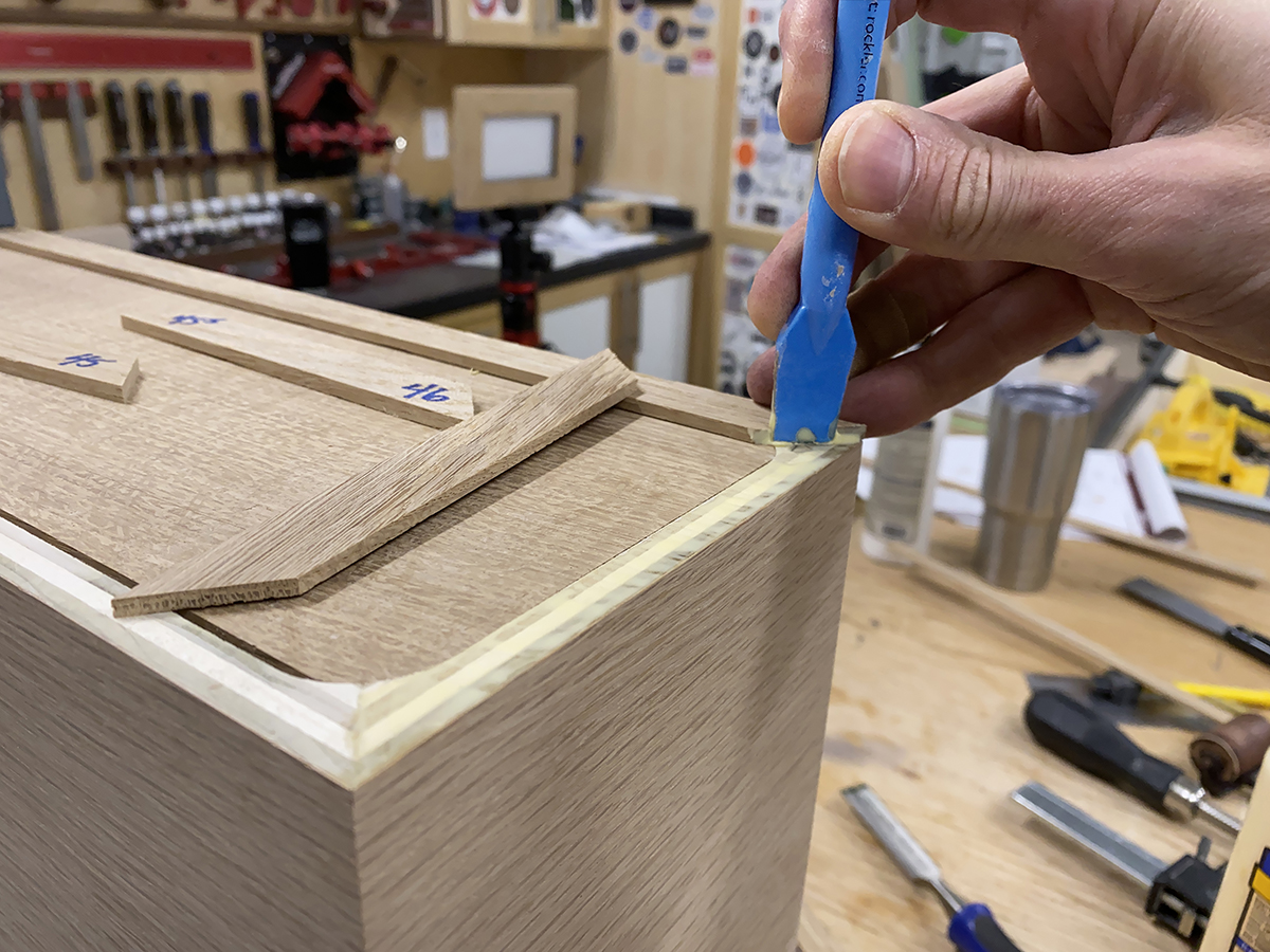
With the back of the case sealed up, it was time to move on to creating the beveled edge-banding for the front of the case. For this, I headed back to the router table and chamfering bit. I first milled a board 3/4" thick, about 5" wide and roughly 20" long. I lowered the bit to leave a 1/8” flat edge fillet above the bevel. I cut this profile on both edges of the board, then went to the table saw and set the rip fence to 3/4". I ripped both edges off into a 3/4” strip which left that 1/8” fillet on the bottom of the profile as well. I repeated the process a couple more times, creating several pieces of the beveled molding…more than enough to cover any miscues I might have when cutting the miters.
Front edge banding gets chamfered on router table. Both edges shaped, then ripped on table saw.
Trim ripped for 1/8” filet on both corners.
I saved mitering the trim for an early morning before the day had stressed me out. I started by cutting opposing miters on a couple pieces for the short sides, leaving the other end overhanging by a couple inches. I carefully positioned the two pieces on the case and clamped them in place. I used spring clamps that have a rubber band-like strap in the middle. They’re great when working on any sort of edging. With the two sides in place, I cut the long piece to fit between them perfectly. With the first long piece clamped in place, I carefully cut the two short sides to fit. This left the last long piece (which was the top) till last. I cut it perfectly snug so it had to “snap” it into place. This can be a finicky glue-up if you don’t have the bandy clamps I mentioned, but painter’s tape will work, too. If the tape doesn’t seem to be getting the job done, turn the case upside down on your bench and use some parallel jaw clamps to clamp the whole thing down to the bench. I didn’t use any pins, since this is the presentation side of the cabinet. Once the glue was dry, I used a card scraper to tidy up the inside corners and put a finish-ready surface down the length of all the bevels.
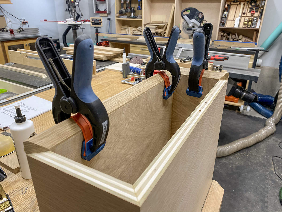
Trim mitered and glued to plywood edge. Spring clamps with straps simplify the job.
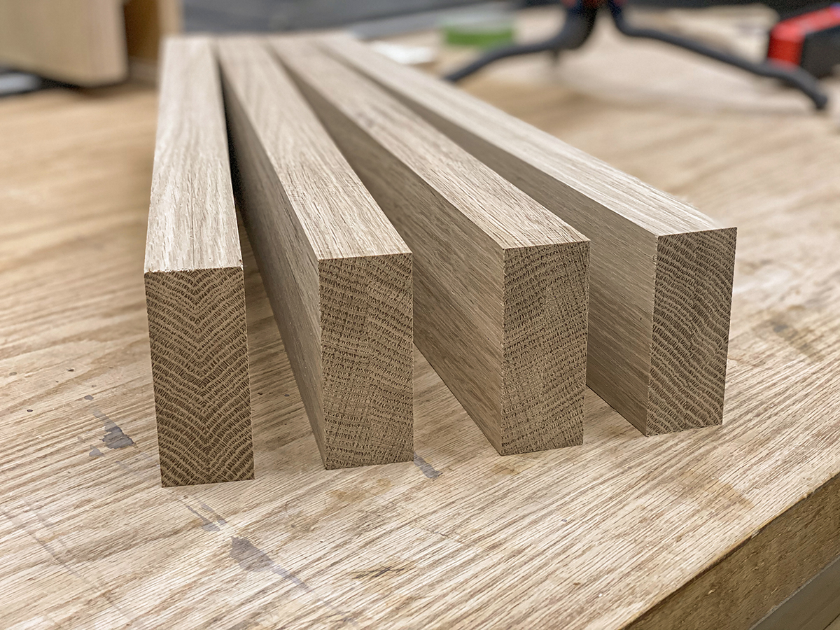
I had trouble locating 8/4 white oak for the legs, so I laminated them. The legs are 1-3/8" thick, so gluing two pieces of 3/4" material together left me plenty of room to joint one face and then mill to final thickness. I used 4" wide stock, which gave me two legs out of each lamination. While the glue laminations were drying in the clamps, I started working on the leg templates.
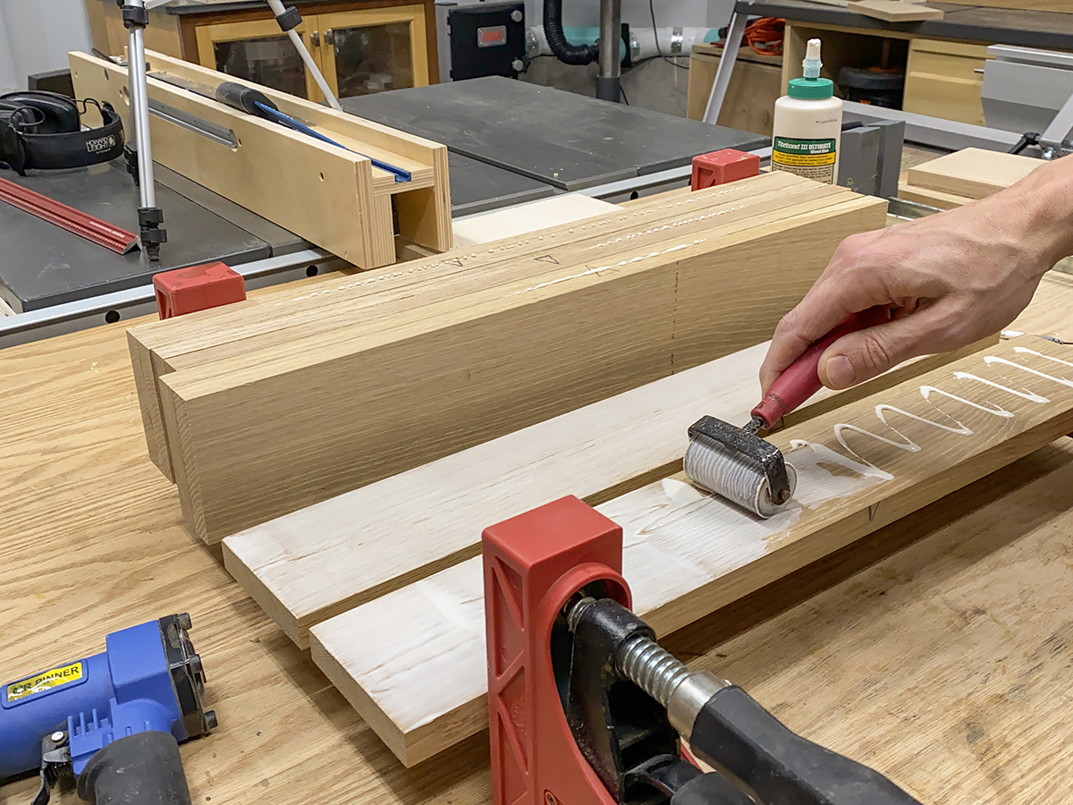
Legs glued and squared up. Planed equal amounts from both sides.
Legs glued and squared up. Planed equal amounts from both sides.
I have a much easier time building projects with multiple angles and tapers if I take the time to make templates. It keeps my head on straight, keeps me from making expensive mistakes on my precious material, lets me match the template to the best grain pattern in my stock and if I ever rebuild the piece, I have a large part of the work already done. I made the leg templates from 3/4” Baltic birch plywood. The angles cut at the top and bottom of the legs are 5 degrees in opposing directions (or 85 and 95 degrees to be geometrically correct). I laid out these angles using my Woodpeckers Bevel Gauge and Angle Reference Plate and then made the cuts on my miter saw. I also cut the template to its final length of 21-7/16". Next, I laid out the width dimensions of 2” at the top of the leg and 1-1/4” at the bottom. I used these marks to line up the cut line on my taper jig and made the cut on the table saw. Note: The leg tapers on the inside - the outside is always the straight edge and sits against the fence - on both the tapering jig and the miter saw. Without touching any settings on the jig, I cut another identical blank. Remember to mark your pieces LEFT and RIGHT to avoid any confusion. These 2 pieces will be the foundation for the fixture that I built next.
Tapers cut on templates for legs.
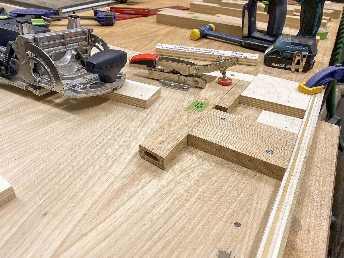
Between splay angles, leg tapers and apron offsets, the seemingly simple leg sub-assemblies get pretty complicated. After struggling with these issues on the original Sophia console table, I decided to build a fixture to keep everything properly aligned and make sure my mating pieces met perfectly this time.
I started the fixture with a piece of 3/4” plywood cut to roughly 24” square. I screwed a cleat along the bottom edge that will act as a stop for the bottom of the legs. The dimension from the inside left leg to the inside right leg should be 15-3/16”. I marked a center point on my bottom cleat and then measured out 7-19/32” in each direction. I placed the inside of each leg on those marks with the feet perfectly flush to the bottom cleat. I cut two large blocks of plywood at 5° (matching the end-cut on the legs) and glued and pinned them down flush with the outside of the leg templates and the bottom cleat. With the leg templates perfectly positioned, I added blocks at the outside top and inside middle, effectively capturing the leg template in perfect position. Next, I measured the angle between the inside of the leg template and the bottom cleat of the fixture. This is where taking the time to build the fixture paid off. According to my SketchUp design, this should have been 7°. But the taper jig apparently wasn’t set up perfectly, because when I used my Bevel Square to take off the angle, it measured just slightly over 7°…not enough to really muck things up, but enough that the joints would have looked sloppy. In the end, it doesn’t matter if the angle is 7° or 7-1/2°…it only matters that the joints mate perfectly.
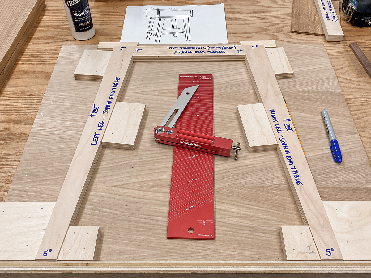
Assembly jig built around the leg templates will simplify real leg glue-up.
So, now that I had the angle figured out, I was ready to make the template for the long (front and rear) aprons. I ripped some plywood to 1-1/2" wide, set my miter saw to the angle on my Bevel Square, and made the long apron template fit perfectly between the two leg templates. In my case, that turned out to be 10-7/16" long point to long point, but don’t try to make yours match the measurement…make it fit your project. Once I got an acceptable fit on all the templates, I added a couple more stop blocks and marked each template with its part name and dimensions.
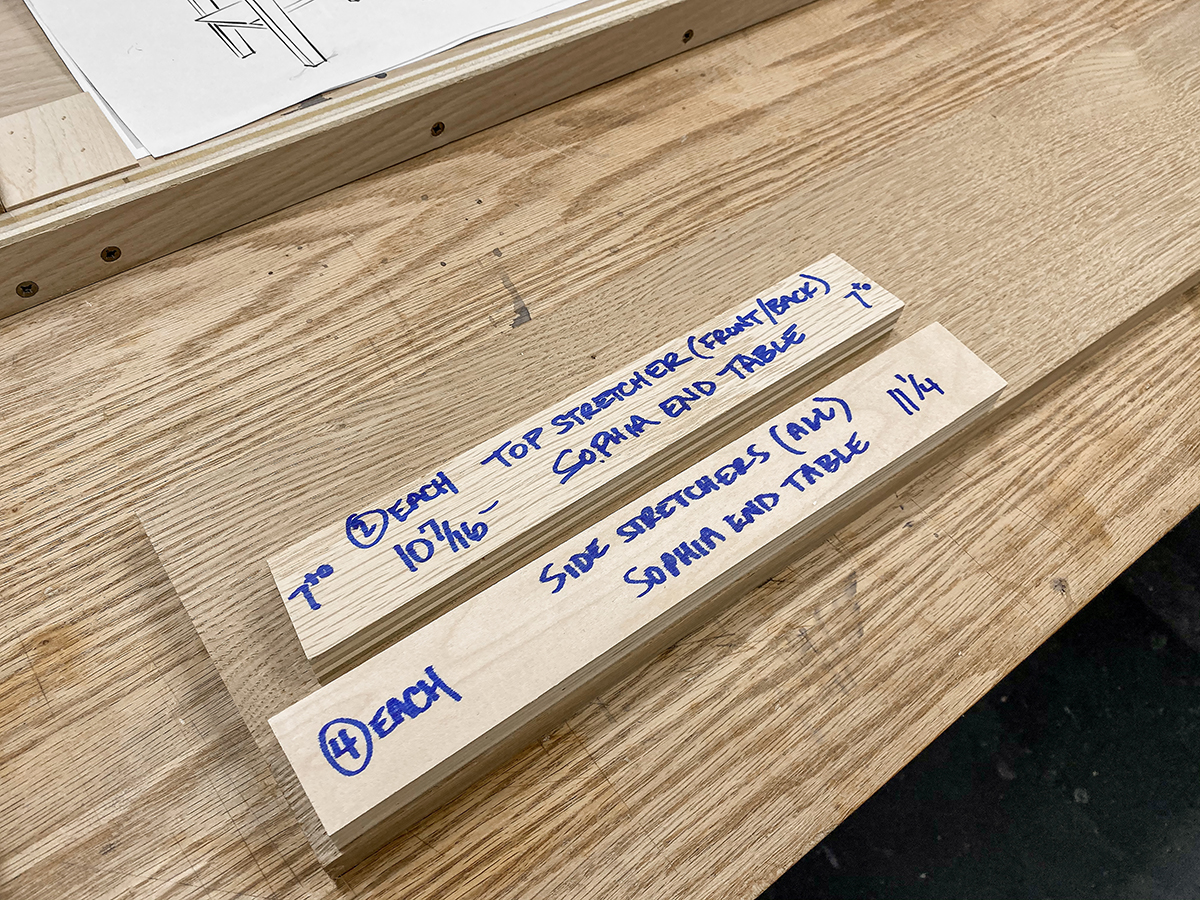
Apron stretcher templates cut to fit in assembly jig then marked.
Next, I used the templates to mark the cuts on the actual leg stock. Each blank yielded 2 legs with the tapers facing each other in the middle of the blank. I marked out all eight legs on the four pieces and then headed to the miter saw to cut the 5° angles at the top and bottom. The legs are also cut to their final length during this process. I had been careful not to touch anything on my table saw since cutting the tapers on the leg templates, so it was a simple matter to clamp each blank into the jig and cut the legs. After cutting the first pair, I dropped them in the assembly fixture with the long apron template. Both joints looked tight. Phew! I finished ripping the other six legs.
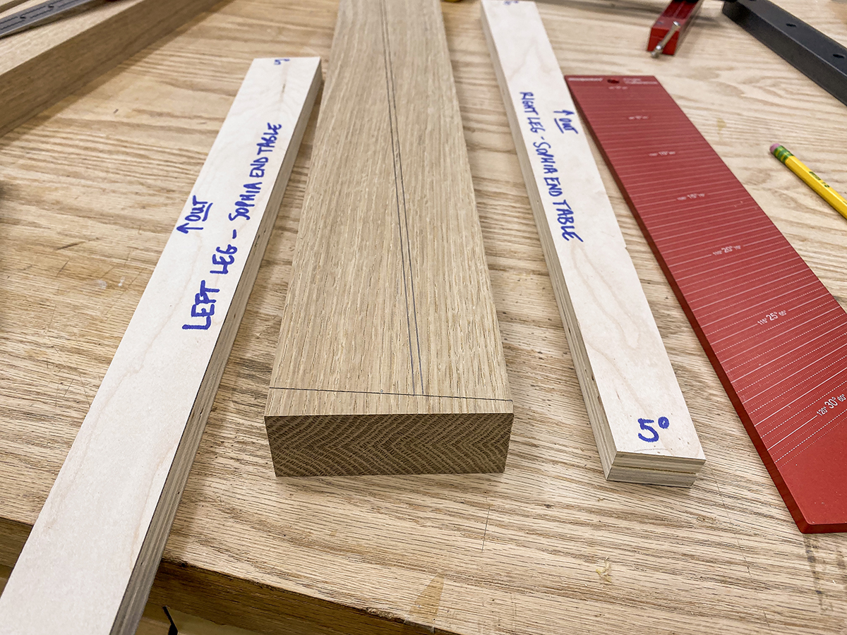
I used the templates to lay out the cuts on the leg material.
While the legs splay when viewed from the front, from the side they’re perpendicular. That means the side aprons (at the top) and the side stretchers (near the bottom) are identical. With templates for just about every part, I decided to make one for these apron/stretchers, too…even though they’re relatively simple. The ends are cut square, but the edges need a 5° bevel to match the leg angle. I grabbed a cutoff of 3/4” plywood, ripped it to 1-1/2" wide and cut it 11-1/4” long and marked it appropriately. I took the two templates and laid them out on my stock to get the most appealing grain pattern for each piece.
Legs cut with taper jig and miter saw. Ready for joinery.
I cut the 4 long aprons to match my trusty template and tested them against the legs in the assembly fixture. For the side apron/stretchers, I ripped down a couple lengths down to roughly 1-3/4”, set the bevel on my table to saw to 5° and ripped one edge. Using a test piece, I ripped the other edge at the opposing 5° so that each face was 1-1/2” wide, sneaking up on the final setting in small steps to make sure I had it right. If you look at the piece from the end grain, it should be shaped like a parallelogram and should fit flush with the ends of the legs when held flush with the edge of the legs. I had to cut eight of these pieces, so I set up a stop block and cut each to 11-1/4” long. Again…don’t trust these measurements…make yours fit.
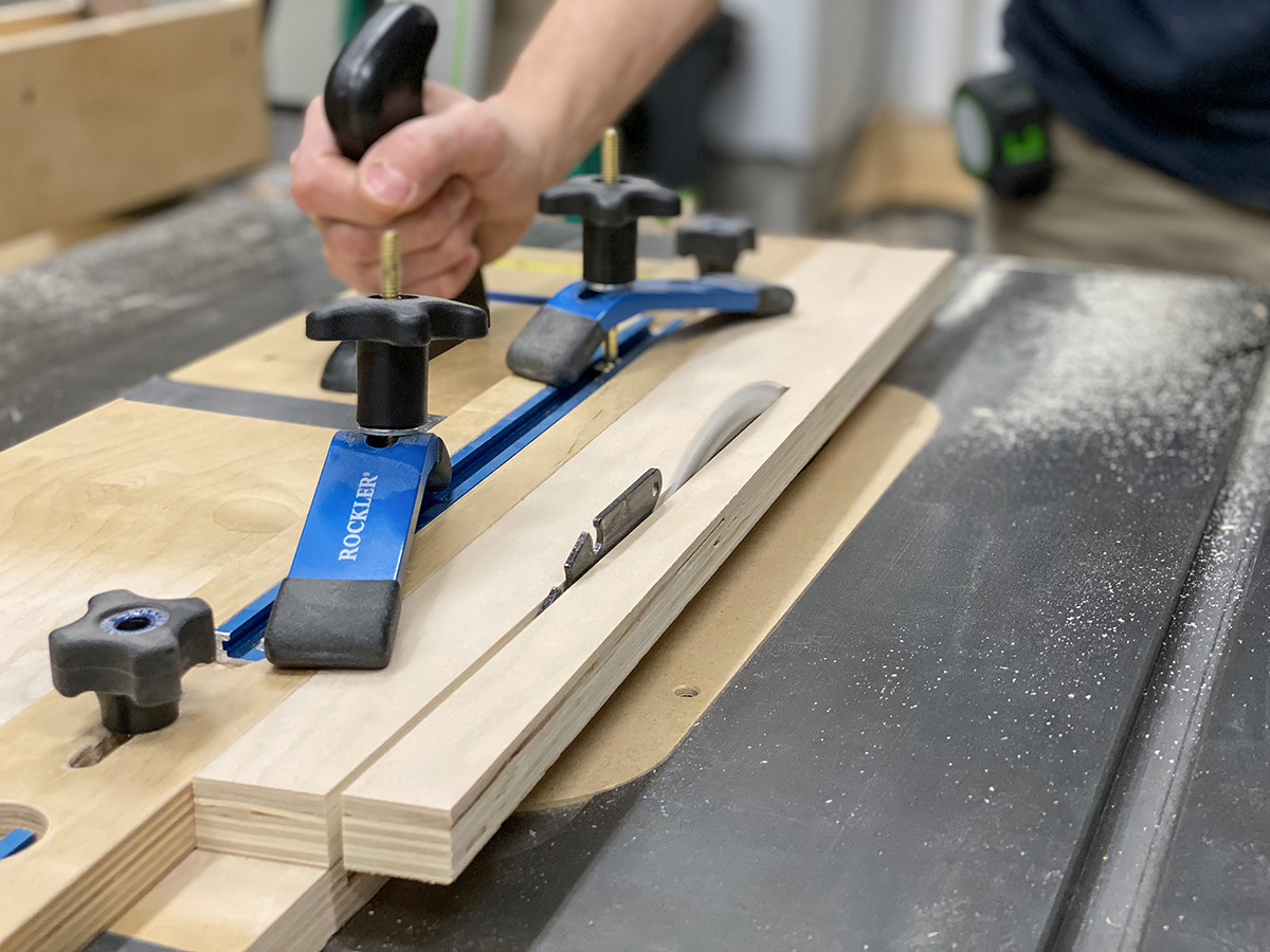
The joinery could be done several different ways, but my favorite for both speed and strength is the Festool Domino. If you don’t have a Domino, these joints could be put together with dowels or pocket holes. The layout procedure will be nearly identical. I started by shimming up the first long apron to be flush with the top of the legs in the assembly fixture. If everything is machined according to design, this should require a 5/8" thick spacer. Getting the apron level with the leg improved the accuracy of marking the centerlines for the Domino mortises. I marked across the joint, removed the long apron, mortised both legs, pulled them out of the fixture and moved to the next set.\
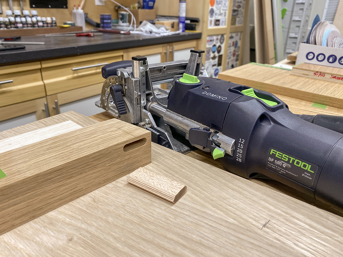
I chose Domino joinery for the legs and aprons. Dowels would work, too.
Let me take just a minute to talk about Domino theory. Part of the beauty of the way the Domino works is that there’s no reason to obsess over getting the mortise precisely centered on your stock. The only thing that matters is using the outside face as the reference for both cuts. (or, as in the case of the side aprons and stretchers, you offset from the outside face the correct amount). Flushing the 3/4" thick top stretchers with the 1-3/8" thick legs is no more complicated than reading a box that says “This End Up”. Make sure your indexing marks are on the outside face and don’t cut if you don’t see a mark.
I modified the assembly jig as needed to secure pieces being mortised.
Okay, back to the action. With the first set of mortises cut into the legs, I made some quick modifications to the leg fixture to hold the long aprons in place while I mortised them. I just put in another block the same thickness as the stretcher so the Domino would have more bearing surface and added a hold down clamp to keep things stationary. I punched those 8 mortises in and started looking at short aprons/stretchers.
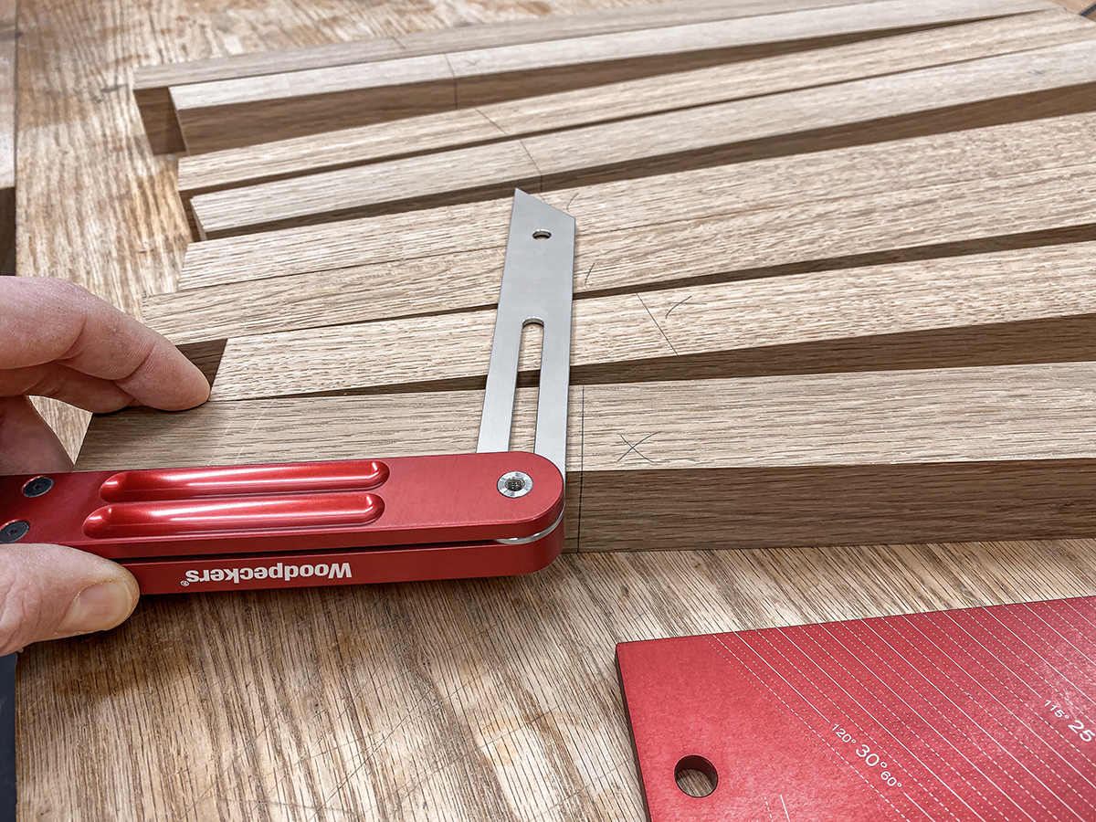
Transferring angles on stretchers.
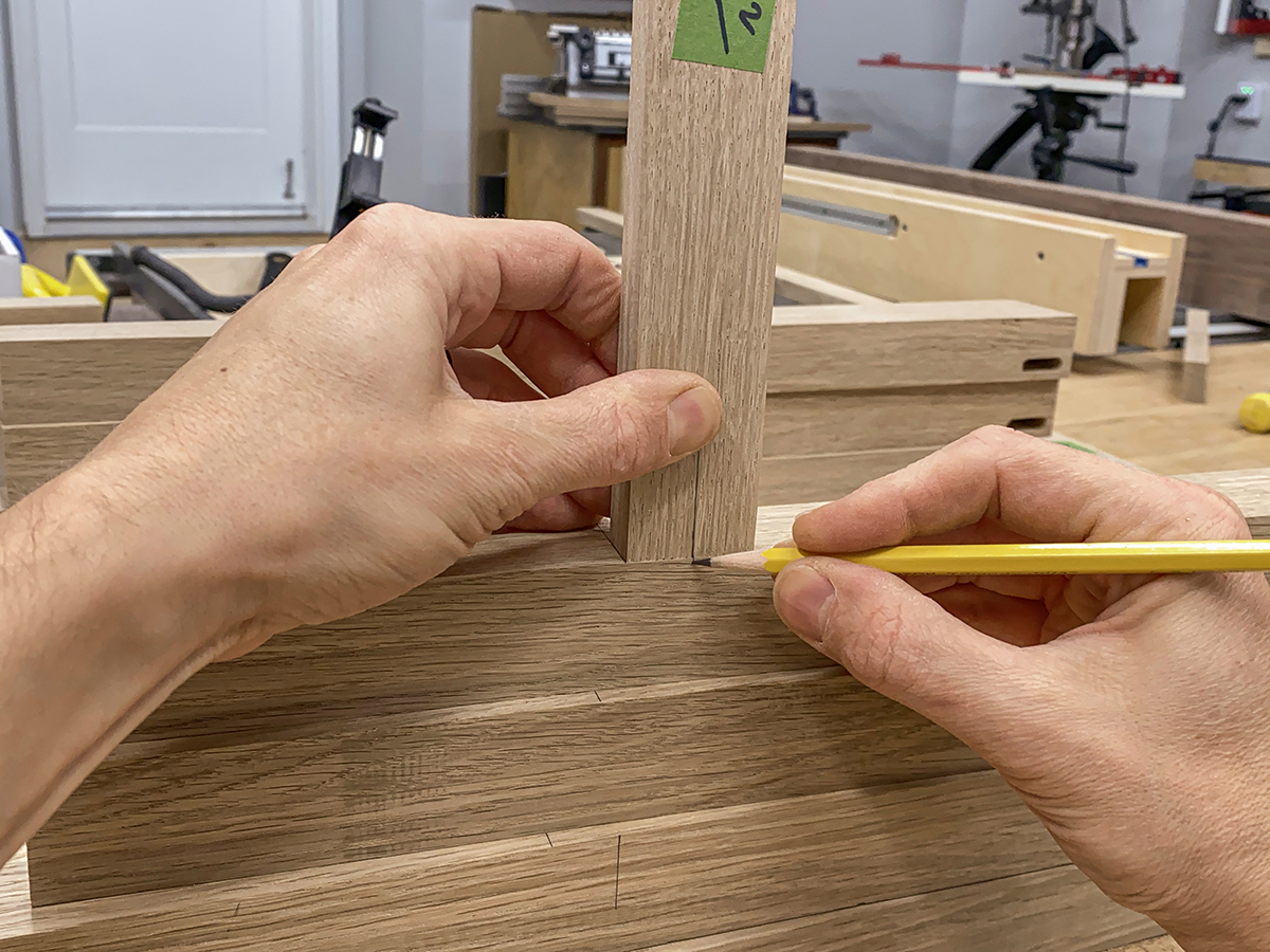
Transferring centerline to leg.
The short aprons start flush with the top of the leg. The short stretchers start 5-1/2” from the bottom of the leg. I started by marking the center of all 8 pieces (remember, on the sides, they’re identical in size and shape with square ends). Then I ganged all my legs together and marked 5-1/2" up from the bottom and transferred the line around to the side with my bevel gauge. I lined up the bottom of a stretcher to the line I had just drawn on the leg and transferred the stretcher’s center mark to the legs, taking care to keep every set paired up correctly. For the short aprons, I flushed them with the top end of the leg and transferred the centerlines.
I mortised all 8 apron/stretchers with the mortise roughly centered on the 3/4" thickness, then adjusted the fence of the Domino to move the mortise 3/16" further from the face before mortising the legs. This insets the short aprons and stretchers the necessary 3/16" from the edges of the legs.
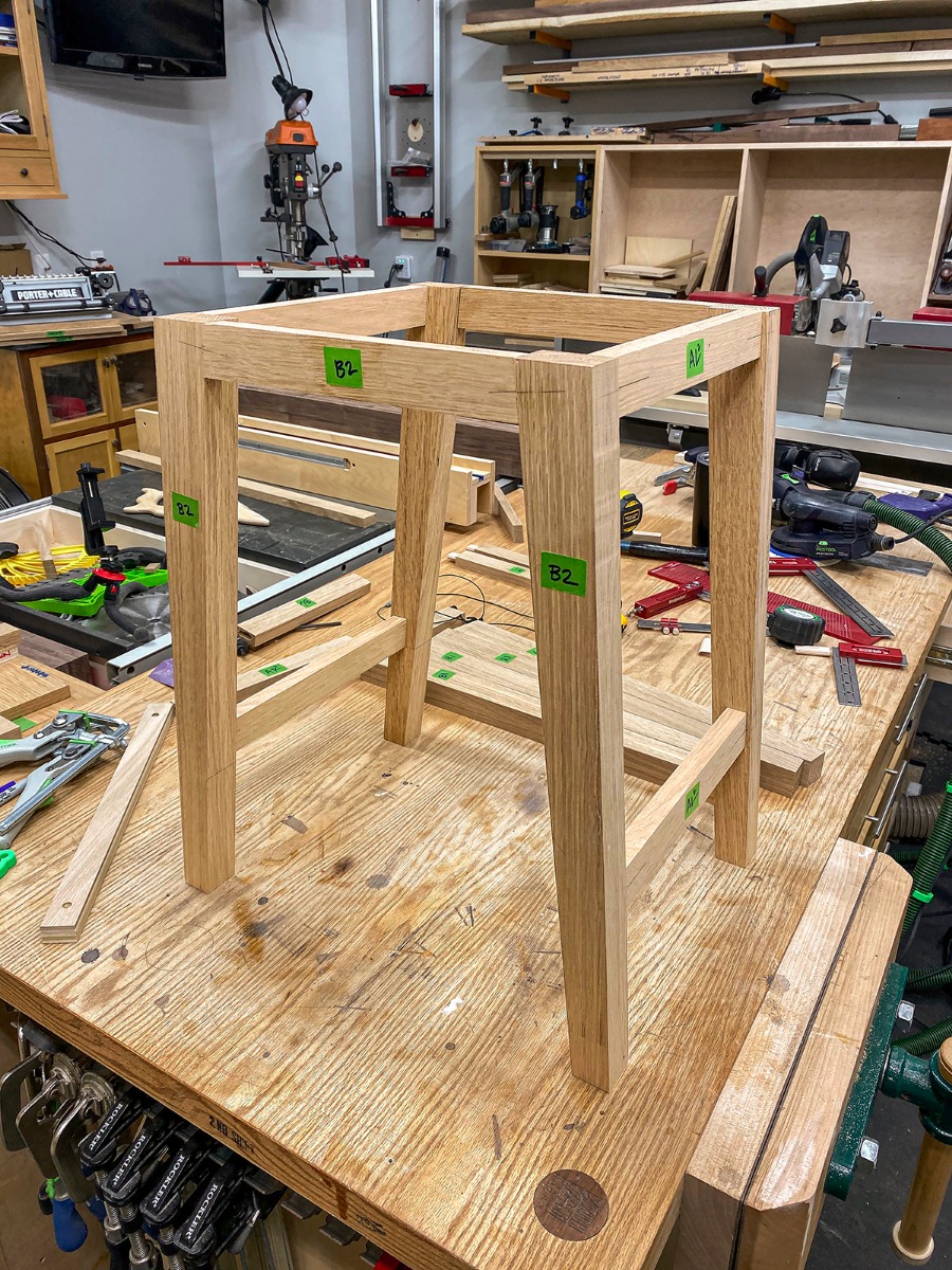
Dry assembly of legs, aprons and stretchers.
At this point, I did a full dry fit of the legs, aprons and stretchers, the piece really started to take shape. The last bit of prep work on the bottom side stretchers was to drill mounting holes for the bottom shelf to be secured. The two holes near the center were left normal size and the outer 2 holes were enlarged to allow for wood movement.
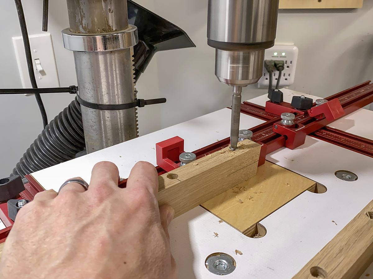
Drilling mounting holes for bottom shelf.
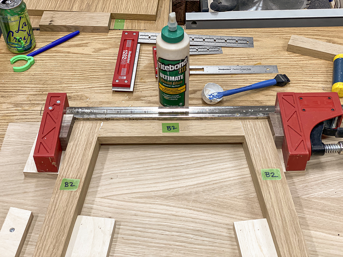
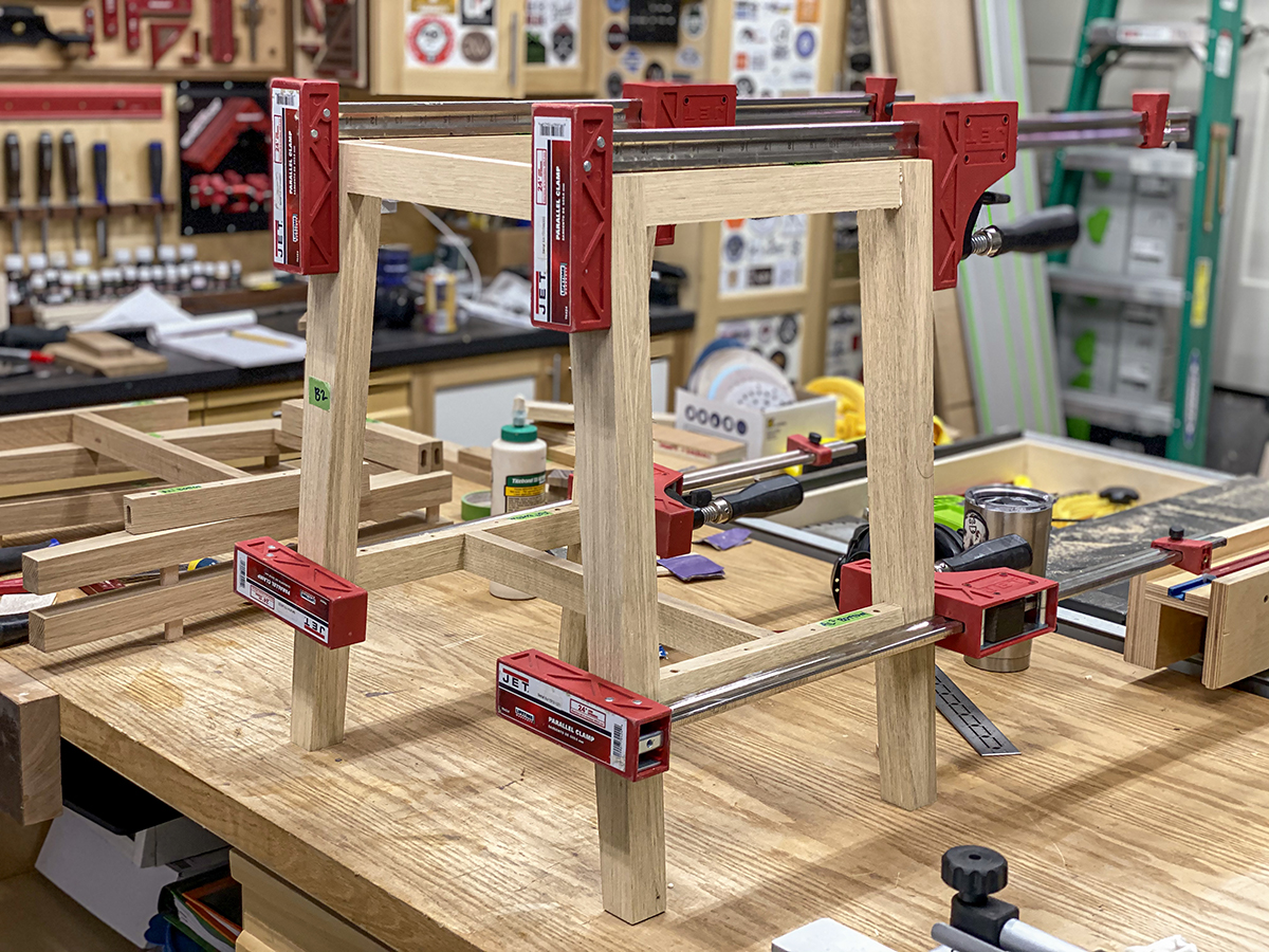
Leg sub-assemblies in jig. Tapered blocks apply clamping pressure evenly.
Before I could cut the single long bottom stretcher that ties the two side stretchers together, I needed to glue up the front and rear leg assemblies. I used my trusty leg assembly fixture to ensure a perfect glue up. Due to the splay angle of the legs, I cut some angled blocks to give me even clamping pressure across the joints. Once the clamp was in place, I removed the assembly from the jig and proceeded to glue up the other three sub-assemblies.
While the glue was drying on the legs, I milled and machined the bottom shelves. These are 3/4" thick, 11" wide and 18-3/4" long. I beveled the ends with the same profile I used for the trim on the cabinets. It’s hard to get a pristine machined surface on white oak end grain, so take a few light passes instead of trying to get it all at once.
Dry assembly to cut and fit the long single stretcher.
I pulled the front and rear leg assemblies out of the clamps and attached the side aprons with some loose Dominos for another dry fit assembly. I used clamps to secure all pieces together so I could measure and cut the center bottom stretcher. The angle on each end should be 5°, but I made a test piece to double check. The test piece looked good so I took a measurement between each long point between the stretchers – 14-3/4”. I marked the angles and length on 3/4" x 1-1/2" stock and made the cuts.
I didn’t want to blow through the sides of the lower stretchers, so I cut some 10mm x 50mm Dominos down to 40mm and cut the mortises in the lower stretchers at 15mm and into the center bottom stretchers 25mm. Alternatively, you could switch to 8mm x 40mm Dominos and not have to go to the trouble of cutting them down. I glued up the long stretchers and the side stretchers in a small sub-assembly to save pain and suffering later during the final glue-up. I used the same 5° clamping blocks I used earlier to provide even clamping pressure across the joint.
With all my sub-assemblies glued, stretchers cut to size and mortises cut, it was time to glue the base assembly together. To make this a little easier I glued all the Dominos into the legs first to reduce my stress level during the final assembly. I then applied glue to all the mortises and the end grain on my stretchers and fit everything together. With 4 clamps on each base assembly, they were glued up in a matter of minutes.
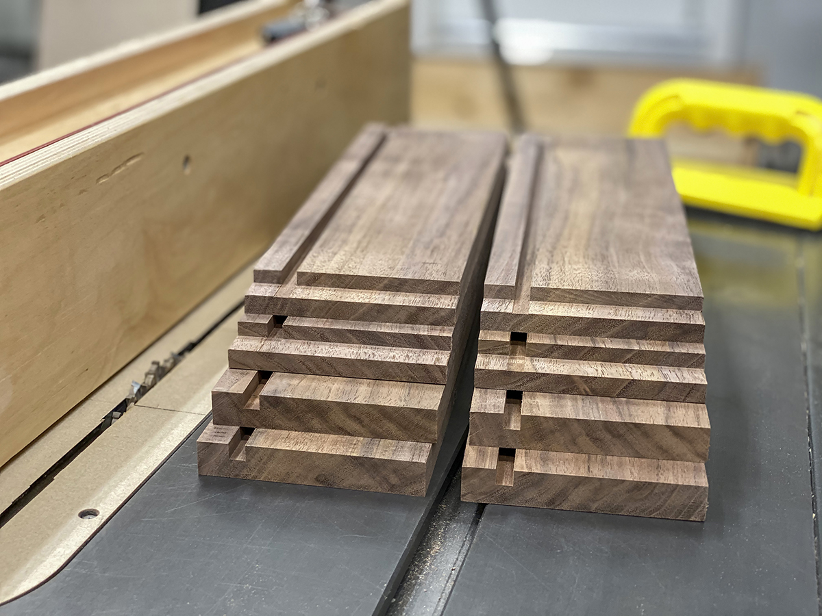
Drawers made from air-dried walnut with maple plywood bottom.
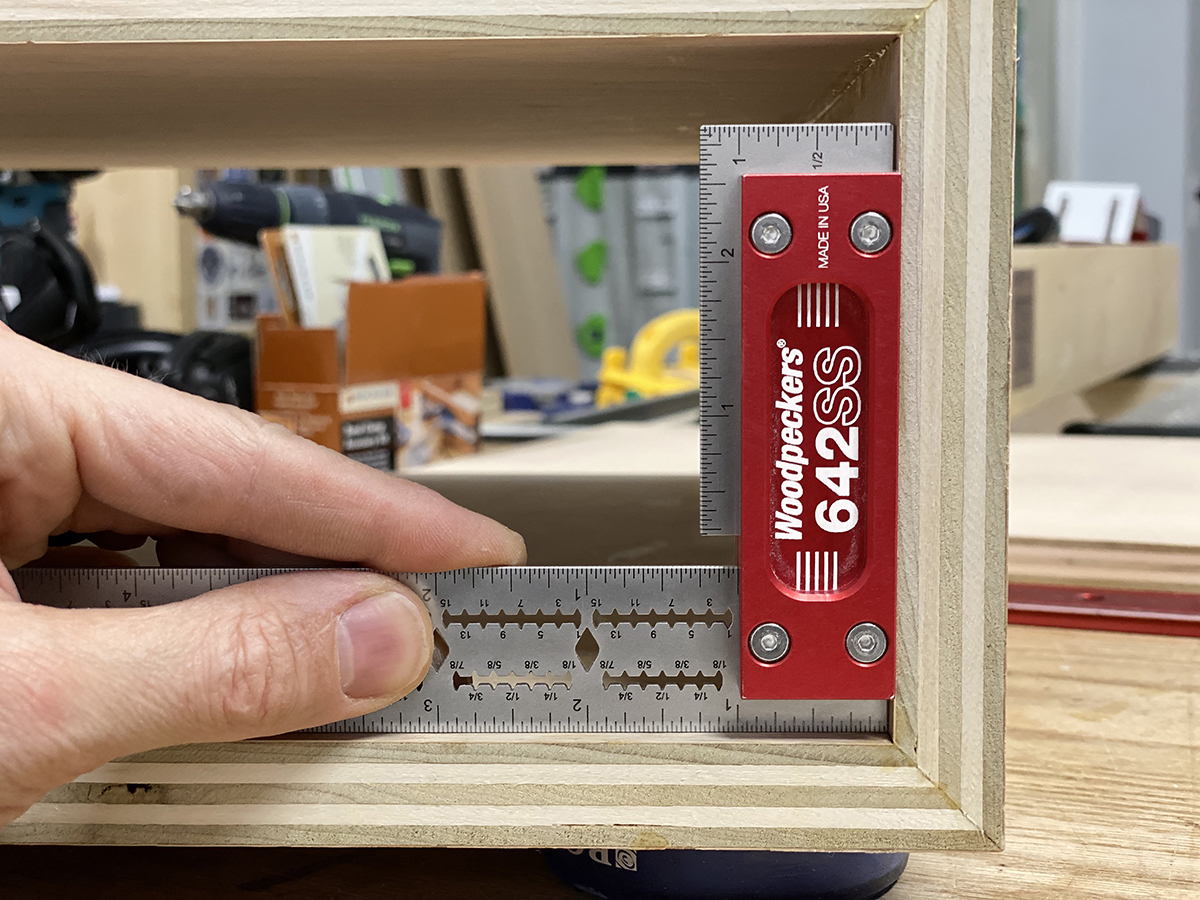
While the glue was hard at work on the bases, I moved on to making the 2 drawer boxes. I used air-dried walnut for all four sides and 1/4” maple plywood for the drawer bottom. I used a simple rabbet joint for all four corners. Before gluing the drawer together, I sanded all of the inside faces, including the plywood. I used the Woodpeckers CSP Clamps and the Clamping Squares Plus to get perfectly square joints during the glue-up.
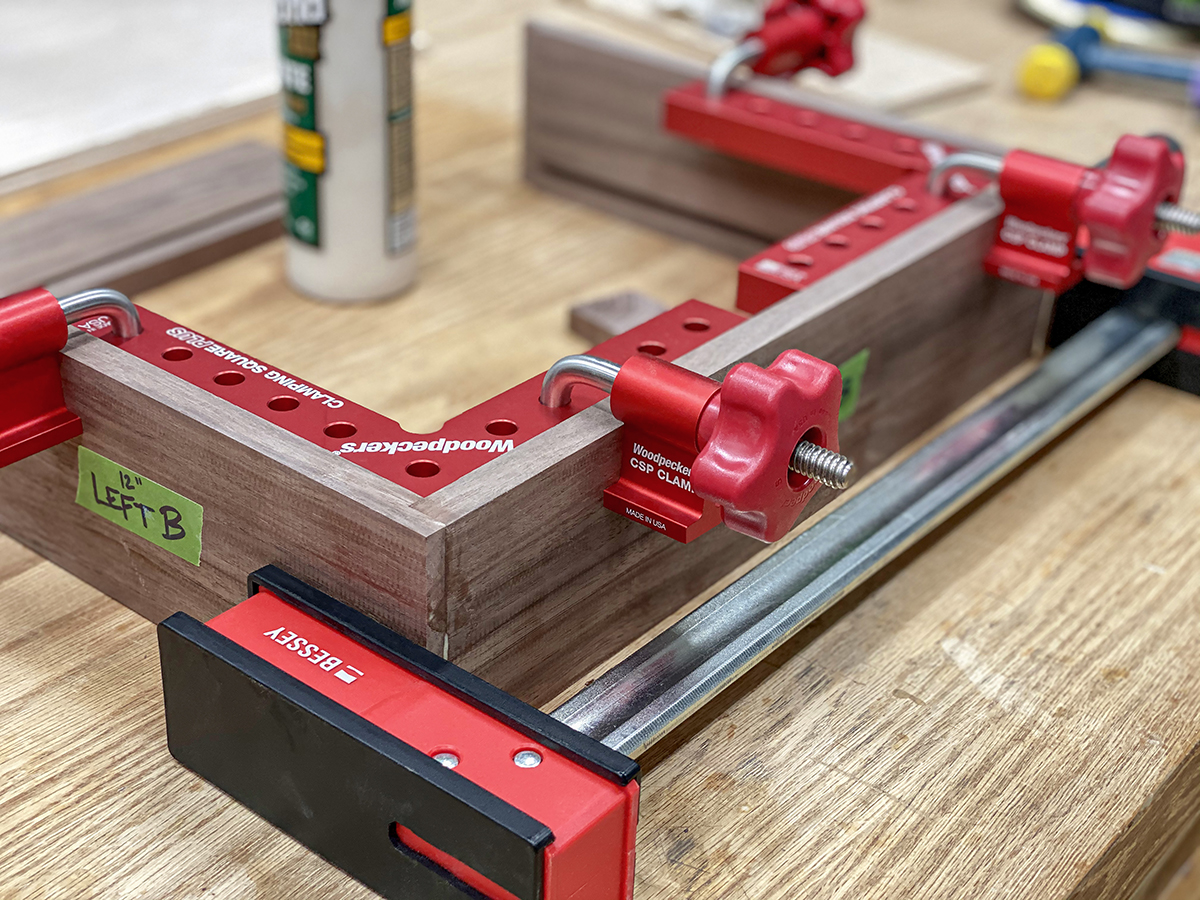
Drawers assembled and squared around Clamping Squares Plus.
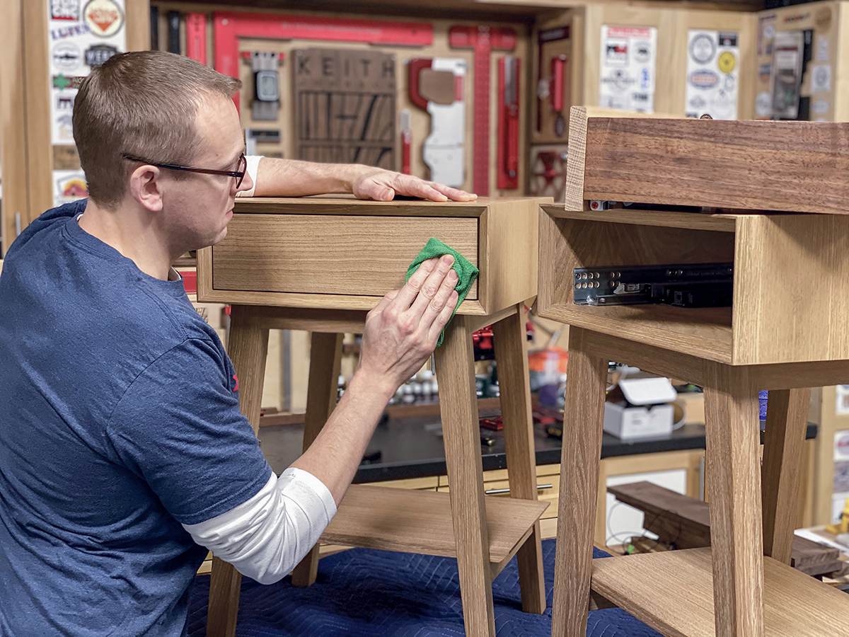
Once the glue was dry on the drawers, I detailed the outside of both boxes to remove any glue and flush up any inconsistencies in the joinery. I used Blum undermount slides with a tip-on attachment which provides a “push to open” function. Like the original Sophia console table, I didn’t want this piece to have any knobs or handles to open the drawers. I mounted all the provided hardware to do a test fit and ensure smooth operation of the slides.
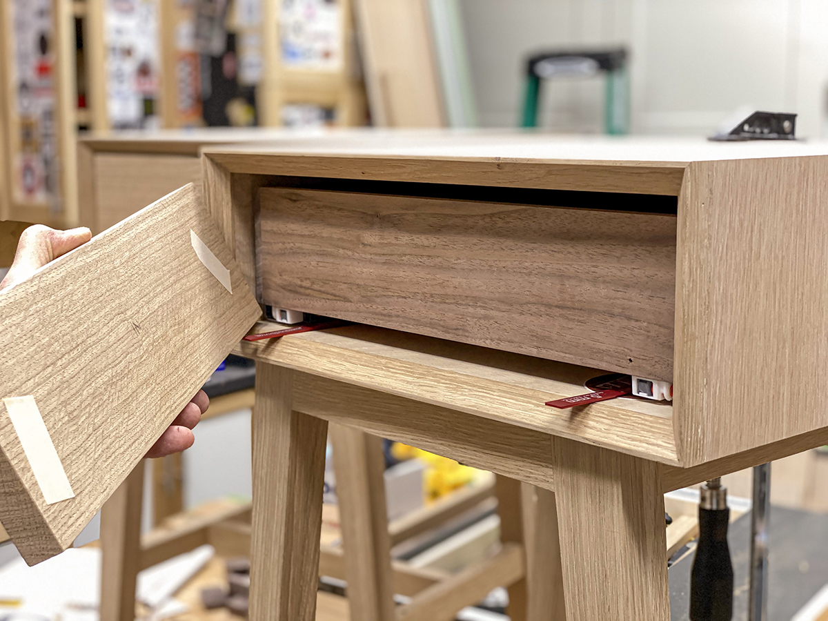
Drawer fronts spaced evenly using Setup Blocks and double-faced tape.
The false fronts for the drawers were made from white oak to match the rest of the piece. I measured the opening and made the drawer front 1/8" smaller both directions, leaving a 1/16" reveal all around. With a couple Woodpeckers Setup Blocks to ensure perfect spacing, I applied double sided tape the back of the drawer face and slid into place. With a little pressure, it was adhered to the drawer box. I used the “push to open” feature to pop out the drawer and then screwed the front to the box with a few screws. This will have to be disassembled before applying finish, but my screw holes with serve as guides for perfect placement when it is reassembled. If my reveals are slightly off, the Blum slides have multi-directional adjustments to zero it back into position.
The last step before applying finish was to sand everything. Luckily, I had done the majority of sanding before assembly to make this process easier. I used a piece of 150 grit paper to smooth all surfaces by hand and break any sharp edges. For the finish, I used Rubio Monocoat in Smoke 5% to all parts, except the walnut drawer box. This was finished with Rubio Pure. The White 5% does not go well with walnut. As the product name implies, this is a “one-coat” oil-wax finish, but I like to apply a second coat to give it a little bit more sheen. I waited 3 days before doing this with a very light sanding with 320 grit between coats. The final step was to attach the bottom shelves and the upper drawer cabinets to the bases. I used wood screws for the shelves and “figure 8” desktop fasteners for the drawer cabinets.
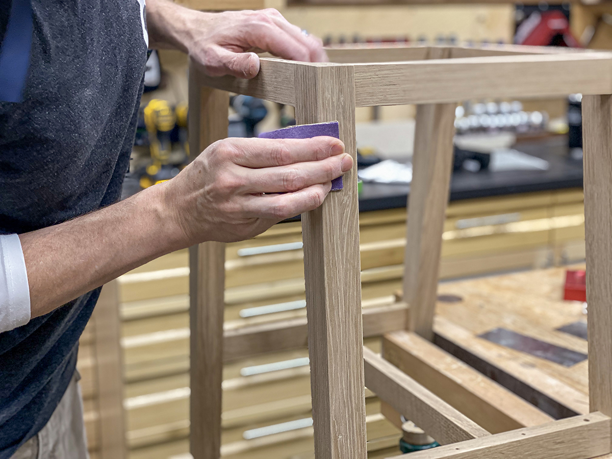
Final sanding and detailing before applying the finish.
As I was finishing the end tables, I realized this was probably my quickest build in recent memory (and two pieces at that!). I enjoy the prototyping process, experimenting with small details, and winging it a little with new designs, but that can be very time-consuming. Sometimes it can be rewarding to make a plan and execute it without going off road every step of the way. I’m not sure which is better, but I haven’t heard my cats complain about all the new furniture and places to nap. Now, if I could only get them to start using coasters...
Finished and ready to go in the bedroom.
![]()